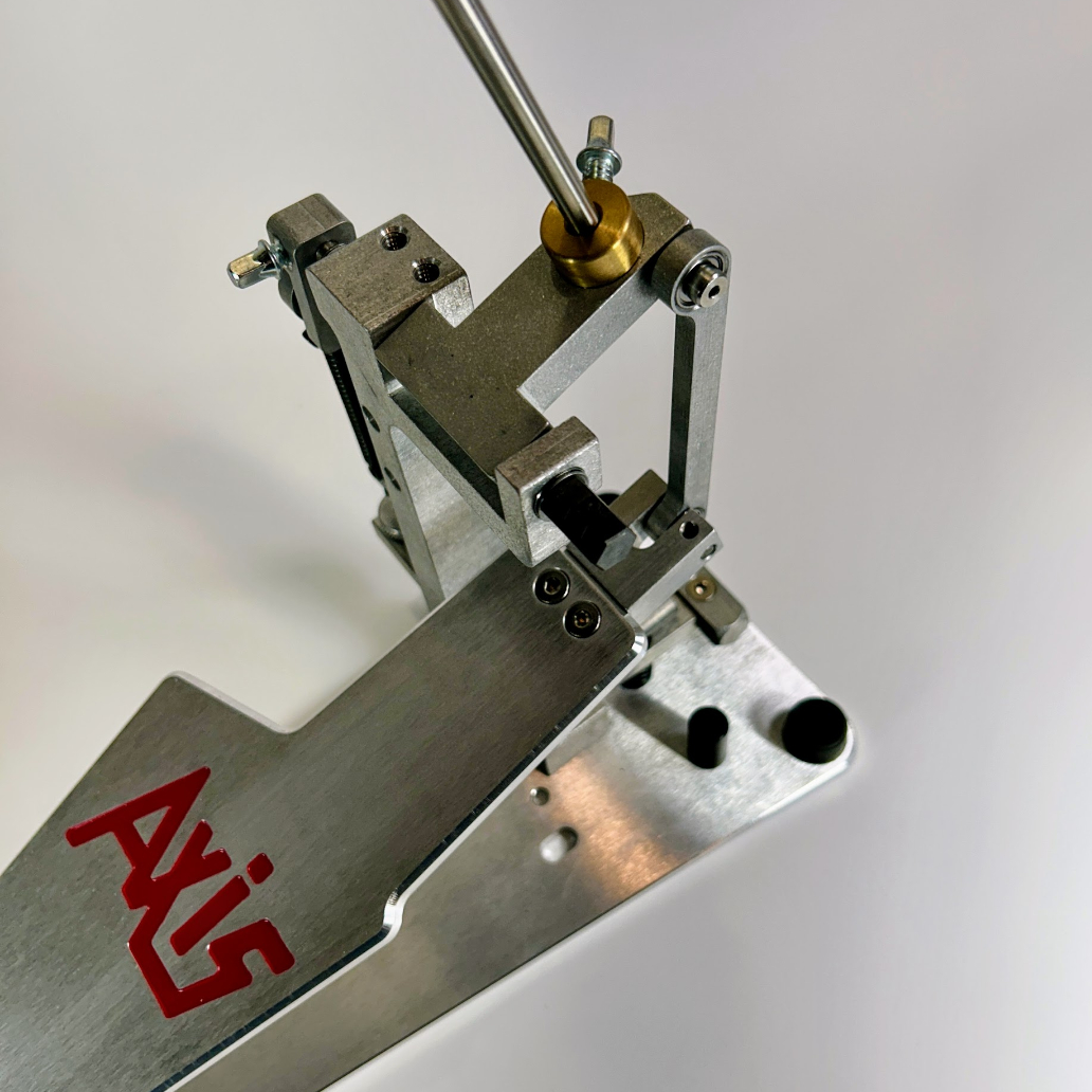
All AXiS pedals are availble in three (3) CAM configuration : X-CAM, A-CAM and A21-CAM. While each CAM provides a unique feel and playing dyamic, there are drummers from all music geners playing each of our pedal confiterations. Ultimately, what you play and how you play is a very individual choice. We hope the below overview is helpul, if not please don't hesitate to reach out to our team via the Contact Us function at the bottom of the page.
![X-CAM]()
The AXiS X-CAM is a fixed-position, non-adjustable CAM. The angle of the footboard is
matched to the angle of the CAM and the beater is set at a 90-degree angle to the CAM
itself. Adjustments include spring tension and beater angle. The X-CAM is the choice
for many jazz, rock and hard rock drummers. As smooth and responsive as any AXiS
Peadl, the AXiS X-CAM has been the workhorse of rock and roll drummers since it was
introduced in 1990.
The AXiS A-CAM incorporates our patented Variable Drive Lever (VDL), allowing you to adjust the angle of the footboard independently of the beater angle. This simple adjustment alters the amount of footboard travel required to activate the beater, offering a range of feels from fast and responsive to slow and controlled. Minor adjustments in the VDL yield noticeable differences in how the pedal plays, giving you precise control to dial in the pedal for your individual playing style.
The AXiS A21-CAM is a unique CAM design that offers enhanced power and velocity. By shifting the beater throw angle 21 degrees forward, you are able to generate more force behind the beater stroke. Originally designed for drummers who wanted to play fast without sacrificing power, the A21-CAM has been adopted by drummers of all genres given its unique properties of speed, power and control. This CAM design also incorporates our patented Variable Drive Lever (VDL), allowing you to adjust the angle of the footboard independently of the beater angle. This simple adjustment alters the footboard travel required to activate the beater, offering a range of feels from fast and responsive to slow and controlled. Minor adjustments in the VDL yield noticeable differences in how the pedal plays, giving you precise control to dial in the pedal for your individual playing style.


